Setting up SNMPv3 on Cisco IOS and Juniper JUNOS

Clear text unencrypted management protocols such as SNMPv1 or SNMPv2 are getting depreciated. I was a big fan of SNMPv2c for ages – it was easy to configure and worked well!

This is my SNMPv3 configuration example document for both Cisco and Juniper devices.

SNMPv3 Security Levels

We need to understand SNMPv3 security levels before we configure it. Following are the three supported security levels of SNMPv3.

(i) noAuthNoPriv – no auth, no data encryption crypto; no password required to set this up
(ii) authNoPriv – use SHA or MD5 password for auth, but no data encryption crypto; so, no password is required for data encryption
(iii) authPriv – use SHA or MD5 password for auth and use AES or DES password for data encryption crypto; this is the most secure option.

This document is based on “authPriv” with SHA for the password and AES for the data crypto. Let’s move on to the setup sections……

Setting up SNMPv3 on a Cisco IOS

The steps are simple and straightforward –

Step 1: Create an SNMPv3 view
Step 2: Create an SNMPv3 group that has access to the recently created view
Step 3: Create a user, and add it to the above group with an auth and data encryption passwords; we can add an ACL here as well to restrict the source.

!
Following are the attributes used in this example -

SNMPv3 UserName: test-snmp3-user
SNMPv3 GroupName: test-snmp3-grp
SNMPv3 AuthPassword: AUTH_PASSWD
SNMPv3 CryptoPassword: CRYPTO_PASSWD
SNMP ViewName: TESTSNMP3VIEW
!
!
conf t
!
ip access-list standard acl-snmp-ro
remark SNMP read access
permit 10.10.1.0 0.0.0.255
permit 10.11.10.0 0.0.0.255
!
!--SNMPv3 specific params--
snmp-server view TESTSNMP3VIEW iso included
snmp-server group test-snmp3-grp v3 priv read TESTSNMP3VIEW
snmp-server user test-snmp3-user test-snmp3-grp v3 auth sha AUTH_PASSWD priv aes 256 CRYPTO_PASSWD access acl-snmp-ro
!
!--following are generic SNMP params--
snmp-server trap-source GigabitEthernet0
snmp-server source-interface informs GigabitEthernet0
snmp-server location "Equinix SY3"
snmp-server contact nocsupport@company.com
!
!--SNMP show commands--
show snmp
show snmp user
show snmp group
!

Setting up SNMPv3 on a Juniper JUNOS

The following are the steps –

Step 1: Create an SNMP view that includes the OIDs
Step 2: Create an SNMPv3 user and a group with passwords for AUTH and CRYPTO
Step 3: Map the SNMPv3 user to the SNMPv3 group created for security access
Step 4: Set access for the group to the security context (default) with access to the view/OIDs

#
#The SNMPv3 params are same as the Cisco example 
#

set snmp view TESTSNMP3VIEW oid .1 include

set snmp v3 usm local-engine user test-snmp3-user authentication-sha authentication-password AUTH_PASSWD
set snmp v3 usm local-engine user test-snmp3-grp privacy-aes128 privacy-password CRYPTO_PASSWD

set snmp v3 vacm security-to-group security-model usm security-name test-snmp3-user group test-snmp3-grp
set snmp v3 vacm access group test-snmp3-grp default-context-prefix security-model any security-level authentication read-view TESTSNMP3VIEW
set snmp v3 vacm access group test-snmp3-grp default-context-prefix security-model any security-level privacy read-view TESTSNMP3VIEW

#
#--following are generic SNMP syntaxes requires on JunOS--

set snmp description HOSTNAME-OF-DEVICE
set snmp location "Equinix SY3"
set snmp contact "nocsupport@company.com"

#

show snmp v3

#
Notes on the JUNOS syntax:
NOTE 1: After applying the above the command syntax, the "authentication-password" and "privacy-password" will get converted to -> "authentication-key" and "privacy-key"; in-case of COPY/PASTE of the syntax from a running Juniper devices - this needs to be fixed before applying.

NOTE 2: If the SNMP interface is in a "non-default" routing-instance, then you must configure SNMPv3 access to the "non-default" security context (i.e. routing-instance); example syntax following -

#
set snmp v3 vacm access group test-snmp3-grp context-prefix NAME-OF-CONTEXT-Routing-Instance security-model any security-level authentication read-view TESTSNMP3VIEW
set snmp v3 vacm access group test-snmp3-grp context-prefix NAME-OF-CONTEXT-Routing-Instance security-model any security-level privacy read-view TESTSNMP3VIEW
set snmp routing-instance-access
#
#

Testing the SNMPv3 Configs

Linux SNMPWALK can be used to test and verify the SNMPv3 configs above. Run the following command from Linux CLI.

snmpwalk -v3 -l authPriv -u test-snmp3-user -a SHA -A "AUTH_PASSWORD" -x AES -X "CRYPTO_PASSWORD" IP-Addr-of-Cisco-Juniper-Device

Let’s Add the Devices to a Monitoring System

In this example – I add the devices to LibreNMS monitoring system. We need the IP address of the devices and the SNMPv3 params that we applied during the above configs.

Now we should see device details (cpu, memory, traffic, interfaces, routing……) in the LibreNMS!

Make sure SNMP has been enabled on the device’s network interface and also there is no firewall rule that could block SNMP port UDP/161 access from the LibreNMS to the -> Cisco or Juniper devices.

My BGP Notes – Part 2

This is part 2 of “My BGP Notes” series; the part 1 link is here My BGP Notes – Part 1

Part 2 is also my notes on BGP fundamentals; this covers “BGP Neighbor States” and “BGP AFI, SAFI”.

Part 2.1 – BGP Neighbor States

BGP uses the Finite State Machine (FSM) to maintain a table of all BGP peers and their operational status; the FSM model defines – “what actions” should be taken by the BGP engine and “when” in the simplest manner.
 
BGP sessions are peer-to-peer sessions between neighbors; BGP neighbor states are the followings:
 
i. Idle
ii. Connect
iii. Active
iv. OpenSent
v. OpenConfirm
vi. Established

“Idle” State
 
->This is the first stage of the BGP FSM; the Idle state occurs when someone configures a new BGP neighbor or resets an “Established” peer session.
->In this state, BGP detects a start event, listens for a new connection (TCP/179) from a peer, and initiates a TCP connection to remote peer.
->When successful, BGP moves onto the next state “Connect” state.
->If an error causes BGP to go back to the “Idle” state for a second time, the “ConnectRetryTimer” is set to 60 seconds and must decrement to zero before the connection is initiated again. Further failures leave the “Idle state” result in the “ConnectRetryTimer” doubling in length from the previous time.

“Connect” State
 
->In this state, BGP waits for the 3-way TCP handshake to complete successfully.
->Upon a successful TCP connection, BGP sends an “OPEN” message to peer and moves onto next “OpenSent” state.
->If the above TCP connection fails, then BGP goes next to “Active” state and resets the “ConnectRetryTimer” timer.
->If any other input is received, BGP goes back to “Idle” state.
 
During this stage, the neighbor with the “higher IP address” manages the connection. The router initiating the request uses a dynamic source port, but the destination port is always TCP/179.

“Active” State
 
->In this state, BGP speaker tries to connect to peer by initiating “another” new TCP 3-way handshake.
->If a TCP connection is established, an “OPEN” message is sent, the Hold Timer is set to 4 minutes (on Cisco), and the state moves to next “OpenSent” state.
->If this attempt for TCP connection fails, the state moves back to the “Connect” state and resets the “ConnectRetryTimer”.
->If any other input is received, BGP goes back to “Idle” state.

“OpenSent” State
 
->In this state, an “OPEN” message has been sent from the originating router and is awaiting an “OPEN” message from the peer. After the originating router receives the “OPEN” message from the peer, both “OPEN” messages are checked and compared for errors.
->The items are being compared “what is configured” on the peers are: BGP Versions/RID/ASN/Security Params/TTL/SourceIP/and similar params.
->Upon successful “OPEN” messages exchange, BGP sets the Hold Time (using the lower value) and a “KEEPALIVE” message is sent; BGP then goes onto next “OpenConfirm” state.
->If an error is found in the “OPEN” message, BGP sends a “NOTIFICATION” message and the state is moved back to “Idle” state.
->If TCP receives a disconnect message, BGP closes the connection, resets the “ConnectRetryTimer”, and sets the state back to “Active”.
->If any other input is received, BGP goes back to “Idle” state.

“OpenConfirm” State
 
->In this state, BGP waits for a “KEEPALIVE” message or “NOTIFICATION” message from peer.  
->Upon successful receipt of a peer’s “KEEPALIVE” message, the state moves next to “Established” state.
->If the hold timer expires, a stop event occurs, or a “NOTIFICATION” message is received, then the state is moved back to “Idle” state.

“Established” State

->In this state, the BGP session is established.
->BGP neighbors exchange routes via “UPDATE” messages.
->As “UPDATE” and “KEEPALIVE” messages are received, the Hold Timer is reset.
->If the Hold Timer expires or an error is detected (a “NOTIFICATION” message), BGP moves the neighbor state back to the “Idle” state.

In summary; if no error, then BGP neighbor state progressions are the followings:

Idle -> Connect -> OpenSent -> OpenConfirm -> Established.
 
If there any error occurs, then BGP neighbor state progressions “could be” the followings:

Idle -> Connect (back to “Idle”) -> Active (back to “Connect” or “Idle”) -> OpenSent (back to “Active” or “Idle”) -> OpenConfirm (back to “Idle”) -> Established (back to “Idle”).

The following screenshot is taken on a Cisco CSRv router – BGP “Idle” state:

The following screenshot is taken on a Cisco CSRv router – BGP “Established” state:

Part 2.2 – BGP AFI and SAFI

AFI means “Address Family Indicator”
SAFI means “Subsequent Address Family Indicator”.

They are used in the “Multiprotocol Extensions” to BGP (MP-BGP) and are exchanged during neighbor capability exchange (in the BGP “OPEN” message) during the process of establishing the peers. They basically tell the remote peer what address families (IPv4, IPv6, VPNv4, VPNv6…) and what specific sub-address family (multicast, unicast, vrf, evpn, vpls, flow-spec…) the local BGP router will transport the routes for.

AFI is 16-bit.
SAFI is 8-bit.

A few well-known AFI-SAFI are the followings:

1-1 is for IPv4 (AFI:1) unicast forwarding (SAFI:1)
1-2 is for IPv4 (AFI:1) multicast forwarding (SAFI:2)
1-128 is for IPv4 (AFI:1) VPNv4 (MPLS-labeled VPN address SAFI:128)
1-132 is for IPv4 (AFI:1) VRF – Route Target constrains (SAFI:132)
1-133 is for IPv4 (AFI:1) Flow-spec (SAFI:133)

2-1 is for IPv6 (AFI:2) unicast forwarding (SAFI:1)
2-2 is for IPv6 (AFI:2) multicast forwarding (SAFI:1)
2-128 is for IPv6 (AFI:2) VPNv6 (MPLS-labeled VPN address SAFI:128)

25-70 is for L2VPN (AFI:25) EVPN (SAFI:70)

AFI: 0 is reserved
AFI: 32-16383 are unassigned
AFI: 16400-65534 are unassigned

In the future, there will be many new AFI and SAFI adopted in MP-BGP as new capabilities!

The following screenshot is taken on a Cisco CSRv router – showing available AFIs:

The following screenshot is taken on a Cisco CSRv router – showing available SAFIs within IPv4:

The following screenshot is taken on a Cisco CSRv router – showing available SAFIs within L2VPN:

MP-BGP AFI and SAFI References:
https://www.iana.org/assignments/address-family-numbers/address-family-numbers.xhtml
https://www.iana.org/assignments/safi-namespace/safi-namespace.xhtml

My BGP Notes – Part 1

My BGP notes. It’s going to be a series of posts here….My BGP Notes 1,2,3,……

(Part 2 is here My BGP Notes – Part 2)

I have been keeping BGP notes on many scattered places. A lot of times when I want to refresh my BGP knowledge – I could not find the notes I kept earlier easily and end up Googling (yes, BGP references are everywhere but I prefer my own way of taking notes). Hence, I am adding my BGP notes on my blog page.

To me, BGP is not only a routing protocol but rather BGP is a big “network application” I use in designing networks in enterprise connectivity, data centre networking, and ISP connectivities.

This is “part 1” of my notes; I will start with the fundamentals of BGP.

The Basics

-RFC 1654 defines BGP as an EGP “path-vector” routing protocol.
-BGP is designed for IPv4. (But Multiprotocol BGP – MP-BGP works with IPv6).
-BGP configuration requires Autonomous System Numbers (ASN).
-ASN numbering was originally 16-bits long number (2-bytes); 1-65,535.
-Extended ASN ranges are 32-bit (4-bytes) number up to 4,294,967,294.
-ASN 64,512–65,535 are private within the 2-bytes range.
-ASN 4,200,000,000–4,294,967,294 are private within the 4-bytes range.
-The BGP version we use is BGP v4.
-BGP loop prevention is based on the path-vector mechanism.
-BGP adds its own AS number (AS_PATH) to the prefixes it announces to peers and discards messages if its own AS number is found in a received message.
-BGP advertises routes learned from an eBGP peer to all BGP peers, including both eBGP and iBGP peers.
-BGP advertises routes learned from an iBGP peer to eBGP peers, and not to another iBGP peer. Routes advertisements across iBGP peers can be achieved with the help of a Route-Reflector server.
-Multiprotocol BGP (MP-BGP) supports a wide range of address families besides IPv4 (l2vpn, l3vpn, evpn, unicast, multicast, flow-spec…).

BGP Sessions

-A BGP session refers to the established adjacency between two BGP speaker routers. BGP sessions are always point-to-point between two BGP speakers.
-A BGP session can be iBGP, when a BGP session is established within the same ASN number; both BGP speakers belong to the same ASN.
-A BGP session can be eBGP, when BGP speakers belong to different ASN numbers.
-iBGP administrative distance is 200 whereas eBGP administrative distance is 20.
-BGP speakers do not use Hello packets to discover neighbors like IGP routing protocols.
-A BGP session can not be discovered automatically like OSPF/EIGRP/RIP.
-BGP uses TCP port 179 to communicate with neighbors.
-A BGP session starts with a TCP 3-way handshake.

BGP Messages

BGP speakers use four (04) messages to communicate between themselves.

(01)OPEN message
(02)KEEPALIVE message
(03)UPDATE message
(04)NOTIFICATION message

Some vendor implementations use a fifth message – this is called “Route Refresh” message; however, this is found in the OPEN message for Cisco routers (part of optional capabilities).

BGP messages are easy to identify in captured packets using Wireshark. Let’s see what we found in different BGP messages.

OPEN Message

After the 3-way TCP handshake, the very first BGP message is called “Open”. Both BGP speakers negotiate session capabilities before a BGP peering is established.

Screenshot of OPEN message following.

Based on the OPEN message captured, we found the following items here –

-BGP version
-ASN number
-Hold Time
-BGP identifier (RID)
-BGP capabilities (Multiprotocol extensions, Route refresh capabilities, Graceful Restart capabilities, support for Extended ASN 4-bytes octet)

Notes on Hold Time: BGP default hold time suggested is 90 seconds (3x of keepalive) and keepalives is 30 seconds. BGP default keepalive and hold time are vendor specific these days.

KEEPALIVE Message

Although BGP uses TCP 3-way handshake, it does not rely on TCP connection states (ack mechanism) to check if the peer is still alive.

BGP KEEPALIVE is a simple message format sent every 1/3 of configured Hold Time interval. BGP configuration with 90 seconds Hold Time will send KEEPALIVE every 30 seconds. If Hold Time is set to zero seconds – then there is no KEEPALIVE!

Screenshot of KEEPALIVE message following.

UPDATE Message

BGP network advertisements are included in UPDATE messages. BGP sends both feasible routes and withdrawn routes (previously advertised). Route prefixes and BGP Path Attributes (PA) are found in BGP NLRI. MP_REACH_NLRI and MP_UNREACH_NLRI along with AFI and SAFI details are found in UPDATE messages.

An UPDATE message can act as KEEPALIVE to reduce noise in BGP communications.

Screenshot of the UPDATE message following.

NOTIFICATION Message

NOTIFICATION message is sent if there is an error found in BGP communication between BGP speakers. Notification codes include “Cease”, “Hard Reset” etc.

Screenshot of NOTIFICATION message following.

BGP Message Header

BGP messages header has the following three items –

(01)Marker; this is filled with all fffffffff……16-octets for all message types.
(02)Length; length can be different for different types of message and also based on what information are in the message. The total length is mentioned on the top of the header; breakdowns are in each path attributes section. Min length size is 19 bytes and the max size is 4096 bytes.
(03)Type; Open/Update/Keepalive/Notificaiton.

VXLAN, MBGP EVPN with ingress replication – Part 2 – Configure VXLAN L2 VNI on a single POD

This is the Part 2; Part 1 is here

Example configuration in here are based on Cisco Nexus 9K.

Configurations are very straight forward and simple. As I said earlier – if you have ever configured MP-BGP address families, this will be super easy for you. This doco describes L2 VNI only – there will be another one doco covering L3VNI.

L2 VNI is Type-2 route within EVPN VXLAN – which is “MAC with IP advertisement route”.

L3 VNI is Type-5 route within EVPN VXLAN – which is “IP prefix Route”.

Following is the network topology design diagram I used here in this reference doco.

Notes regarding the network topology-

  • 2 x SPINE switches (IP 172.16.0.1 and 172.16.0.2)
  • 2 x LEAF switches (IP 172.16.0.3 and 172.16.0.4)
  • IP address “unnumbered” configured on the interfaces connected between SPINE and LEAF
  • 2 x VXLAN NVE VTEP interfaces on LEAF switches (source IP 172.16.0.5 and 172.16.0.6)
  • SPINE switches are on the OSPF Area 0
  • LEAF switches are on the OSPF Area 1
  • iBGP peering between “SPINE to LEAF” – mesh iBGP peering topology
  • Both SPINE switches are “route reflector” to the LEAF switches
  • Physical layer connectivity are – “SPINE to LEAF” only. NO “LEAF to LEAF” or “SPINE to SPINE” required. However, “SPINE to SPINE” are optional on a single-pod which can be leverage later on a multi-pod or multi-site EVPN design.
  • VNI ID for this POD-1 is 1xxxx; VNI ID for POD-2 will be 2xxxx. VNI IDs will be mapped to VLAN IDs. Example – VLAN ID 10 mapped to VNI 10010, VLAN ID 20 mapped to 10020.
  • “route-distinguisher (RD)” ID number for this POD-1 is 100; RD ID for POD-2 will be 200.

POD-Underlay-Overlay-SinglePOD-Diag1.2

Before we move to the “step by step” configuration – enable the following features on the Cisco Nexus switches.

Features to be enabled on the SPINE switches –

!
nv overlay evpn
feature ospf
feature bgp
!

Features to be enabled on the LEAF switches –

!
nv overlay evpn
feature ospf
feature bgp
feature interface-vlan
feature vn-segment-vlan-based
feature nv overlay
!

Step 1: Setup Loopback IPs on all the SPINE and LEAF switches

We need “loopback 0” IP address for router ID both for OSPF and BGP. Also, we will be using this loopback IP address for SPINE-LEAF connections as “ip unnumbered” source IP address.

Note: you need to configure OSPF routing first.

SPINE switches-

!---SPINE-01
!
interface loopback 0
description “Underlay – Interfaces and Router ID”
ip address 172.16.0.1/32
ip router ospf VXLAN-UNDERLAY area 0.0.0.0
!
!

!---SPINE-02
!
interface loopback 0
description “Underlay – Interfaces and Router ID”
ip address 172.16.0.2/32
ip router ospf VXLAN-UNDERLAY area 0.0.0.0
!

LEAF switches-

!---LEAF-01
!
interface loopback 0
description “Underlay – Interfaces and Router ID”
ip address 172.16.0.3/32
ip router ospf VXLAN-UNDERLAY area 1.1.1.1
!
!

!---LEAF-02
!
interface loopback 0
description “Underlay – Interfaces and Router ID”
ip address 172.16.0.4/32
ip router ospf VXLAN-UNDERLAY area 1.1.1.1
!

Step 2: Setup OSPF routing and Ethernet interfaces IP address

SPINE-LEAF VXLAN is a “full mesh” network – thus, it is hard to track interface IP addresses if they are configured individually with unique IP address; it will be too many IPs and too many IP Subnets!! IP address “unnumbered” is a nice way to avoid too many IPs and Subnets.

I will be using the same “loopback 0” IP address to all the interconnect interfaces between SPINE & LEAF switches with “ip unnumbered” feature.

Interfaces E1/1 & E1/2 are connected to each other between SPINE and LEAF; SPINE to SPINE connection using interfaces E1/10 & E1/11 on both the switches (as per the above network design diagram).

!---SPINE-01 and SPINE-02
!
interface e1/1,e1/2
no switchport
description “connected to LEAF switches – IP Fabric”
mtu 9216
medium p2p
ip unnumbered loopback0
ip ospf authentication message-digest
ip ospf message-digest-key 0 md5 3 yourOSPFsecret
ip ospf network point-to-point
no ip ospf passive-interface
ip router ospf VXLAN-UNDERLAY area 1.1.1.1
no shutdown
!
!---LEAF-01 and LEAF-02
!
interface e1/1,e1/2
no switchport
description “connected to SPINE switches – IP Fabric”
mtu 9216
medium p2p
ip unnumbered loopback0
ip ospf authentication message-digest
ip ospf message-digest-key 0 md5 3 yourOSPFsecret
ip ospf network point-to-point
no ip ospf passive-interface
ip router ospf VXLAN-UNDERLAY area 1.1.1.1
no shutdown
!
!---SPINE-01 and SPINE-02
!---This is NOT required on a single-POD only solution
!
interface e1/10,e1/11
no switchport
description “connected to SPINE switches – back-to-back IP Fabric”
mtu 9216
medium p2p
ip unnumbered loopback0
ip ospf authentication message-digest
ip ospf message-digest-key 0 md5 3 yourOSPFsecret
ip ospf network point-to-point
no ip ospf passive-interface
ip router ospf VXLAN-UNDERLAY area 0.0.0.0
no shutdown
!
!---all the SPINE & LEAF; adjust the loopback0 IP address for each sw
!
router ospf VXLAN-UNDERLAY
router-id 172.16.0.LOOPBACK0-IP
passive-interface default
!

At this stage – OSPF adjacency should be formed between SPINE and LEAF and SPINE to SPINE switches.

Verify your OSPF configuration and connectivity between switches-

show ip ospf neighbors
show ip ospf route
show ip ospf database
show ip ospf interface

Make sure you able to ping between all the SPINE and LEAF switches.

(Screenshot – “show ip ospf neighbor” from SPINE-01)

OSPF-Neighbors

Step 3: Setup MP-BGP peering across all the SPINE and LEAF switches

I will now configure MP-BGP along with address family “l2vpn evpn” on all the switches; we will have to enable “send-community extended” on all the BGP peer to allow exchange of L2/L3 evpn VXLAN encapsulations.

  • iBGP peering between SPINE-01 and SPINE-02;
  • iBGP peering from all SPINE to LEAF – SPINE switches are route reflector server to LEAF switches
  • NO LEAF to LEAF BGP peering
!
!---SPINE switches MP-BGP config SPINE-01
!---adjust the RID IP address for SPINE-02
!---iBGP to LEAF switches
!
router bgp 65501
  router-id 172.16.0.1
  log-neighbor-changes
  address-family l2vpn evpn
    retain route-target all
  !
  neighbor 172.16.0.3
    remote-as 65501
    description "LEAF-01 - iBGP peer - RR client"
    password 3 ef6a8875f8447eac
    update-source loopback0
    address-family l2vpn evpn
      send-community extended
      route-reflector-client
  !
  neighbor 172.16.0.4
    remote-as 65501
    description "LEAF-02 - iBGP peer - RR client"
    password 3 ef6a8875f8447eac
    update-source loopback0
    address-family l2vpn evpn
      send-community extended
      route-reflector-client
!
!---LEAF switche LEAF-01 
!---adjust the RID IP address for LEAF-02
!---iBGP peering to SPINEs in the same POD only
!
router bgp 65501
  router-id 172.16.0.3
  address-family l2vpn evpn
    retain route-target all
  !
  neighbor 172.16.0.1
    remote-as 65501
    description "SPINE-01 - iBGP peer - RR server"
    password 3 ef6a8875f8447eac
    update-source loopback0
    address-family l2vpn evpn
      send-community extended
  !
  neighbor 172.16.0.2
    remote-as 65501
    description "SPINE-02 - iBGP peer - RR server"
    password 3 ef6a8875f8447eac
    update-source loopback0
    address-family l2vpn evpn
      send-community extended
!

BGP Verification –

show bgp all summary
show bgp all neighbors 172.16.0.1
show bgp all neighbors 172.16.0.2
show bgp all neighbors 172.16.0.3
show bgp all neighbors 172.16.0.4

Make sure BGP peering status is “Established” for all.

(Screenshot – “show bgp all summary” from SPINE-01)

BGP-all-summary-1.1

As of now – all the above configurations are typical routing & interface configurations. Next sections describe VTEP, NVE, VNI & EVPN configurations.

Step 4: Setup NVE interface on the LEAF switches only

NVE interface is the VXLAN VTEP. This only requires to configured on the LEAF switches. VXLAN encapsulation happen on the NVE interfaces.

The VXLAN encapsulation/decapsulation concept is very similar to MPLS “PE” and “P” routers; source “PE” routers encapsulate MPLS labels and transport them over the “P” routers to the destination “PE” routers. Source LEAF switch NVE VTEP interface encapsulate VXLAN packets and transport them over SPINE switches to destination LEAF switch NVE VTEP interface.

NVE interface requires a dedicated loopback interface; we will setup “loopback 1” on both the LEAF and bind them to “NVE 1” interface.

!---LEAF-01
!
interface loopback 1
description “Underlay – NVE VTEP source IP”
ip address 172.16.0.5/32
ip router ospf VXLAN-UNDERLAY area 1.1.1.1
!

!---LEAF-02
!
interface loopback 1
description “Underlay – NVE VTEP source IP”
ip address 172.16.0.6/32
ip router ospf VXLAN-UNDERLAY area 1.1.1.1
!

!---both LEAF-01 and LEAF-02
!
interface nve1
  no shutdown
  description "VXLAN - VTEP interface"
  host-reachability protocol bgp
  source-interface loopback1
!

show-nve-interface

Verification –

>ping loopback1 IP address between LEAF-01 and LEAF-02; make sure they are reachable

show interface nve1; make sure nve1 interface is UP

Step 5: Create VLAN, VNI and configure EVPN

We will create traditional VLAN IDs and name, then associate an unique VNI ID to the VLAN ID; finally, we will configure the VNI ID onto NVE and EVPN.

!---on both the LEAF-01 and LEAF-02
!
vlan 10
name VLAN10-TEST
vn-segment 10010
!
vlan 20
name VLAN20-TEST
vn-segment 10020
!

Now add the above VLAN10 and VLAN20 onto NVE1 and EVPN on both the switches-

!---on both the LEAF-01 and LEAF-02
!
interface nve1
!
member vni 10010
    ingress-replication protocol bgp
  member vni 10020
    ingress-replication protocol bgp
!

!---both the LEAF-01 and LEAF-02
!
evpn
  !
  vni 10010 l2
    rd auto
    route-target import 100:10010
    route-target export 100:10010
  !
  vni 10020 l2
    rd auto
    route-target import 100:10020
    route-target export 100:10020
!

At this stage MP-BGP EVPN start exchange VXLAN encap packets between NVE VTEP peer LEAF switches.

Verification –

show nve peers; make sure its showing remote IP of peer & status is UP
show nve vni; make sure status is UP

show nve interface nve1
show nve vxlan-params

NVE-PIC-01

Following screenshot showing NVE port number on Cisco Nexus UDP/4789 –

VXLAN-port-number

Part 6: Verification – MAC Learning, VLAN, VNI ID, VXLAN, BGP EVPN

This is the final part.

As a part of end-to-end L2 VNI VLAN test & verification – we have configured the interface “E1/15” on both the LEAF switches as a “trunk” and connected two routers and configured VLAN10 on them.

Router-01 interface MAC address is “50:00:00:05:00:00”; this is connected to LEAF-01; this MAC is local to LEAF-01; IP address configured here is 192.168.10.1/24.

Router-01 interface MAC address is “50:00:00:06:00:00”; this is connected to LEAF-02; this MAC is local to LEAF-02; IP address configured here is 192.168.10.2/24.

Let’s verify MAC address learning on LEAF-01 and LEAF-02 for VLAN10 –

>ping 192.168.10.2 from Router-01; same way ping 192.168.10.1 from Router-02

show l2route mac all

show-l2route-mac-all-LEAF-01

show mac address-table (on the NXOS 9000v this command is >show system internal l2fwder mac)

show-mac-address-table

The above command on the LEAF-01 returns the following output –

This shows the local MAC “50:00:00:05:00:00” as “Local” on “Port E1/15

This will show the remote MAC “50:00:00:06:00:00” as “BGP” learned and port is “nve-peer1

The above command on the LEAF-02 will return the following output –

show-l2route-mac-all-LEAF-02

show-mac-address-table-LEAF-02

This shows the local MAC “50:00:00:06:00:00” as “Local and “Port E1/15

This will show the remote MAC “50:00:00:05:00:00” as “BGP” learned and port is “nve-peer1

The folloiwng BGP l2vpn command will show EVPN MAC, VNI ID & Route-Type

show bgp l2vpn evpn vni-id 10010

show-bgp-l2vpn-evpn-vniid-LEAF-01

This above command returns BGP EVPN details for the VNI 10010 (VLAN 10); note the first part *>l[2]” – this specify the type of route which is Type-2 for L2VNI.

The above verificaiton clearly showing remote “Layer 2 MAC address” learning over BGP which is MAC over Layer 3 routing protocol!!

Thats all.

VXLAN, MBGP EVPN with Ingress Replication – Part 1 – Basic Facts, Design Considerations and Security

I found too many reference docs on VXLAN, most of them cover early solutions that do not use MP-BGP EVPN and manage advertisement of BUM traffic (broadcast, unknown unicast and multicast) via multicast. I know people who do not want to run mcast in their network!

Here, I focus on VXLAN with MP-BGP EVPN with ingress replication to manage BUM traffic (VXLAN + MPBGP EVPN + Ingress Replication).

So, What Is “Ingress Replication” Compared To “Multicast” Based VXLAN Solution?

The answer is – ingress replication is called head-end-replication which performs unicast delivery of VXLAN encapsulated packet across remote VTEPs. Unicast replication requires a source VTEP to delivery same data to every single remote VTEPs in “one-to-one” fashion – whereas in multicast a rendezvous point (preferred is PIM-SM RP) defined where all the VTEPs join to receive delivery of VXLAN encapsulated data in “one-to-many” fashion. Multicast has lower overhead and can provide faster delivery compared to unicast; however, multicast is less secure.

MP-BGP EVPN is the next generation solution becoming widely popular in Data Center networks (VXLAN EVPN) and Service Provider networks (MPLS PBB-EVPN).

My plan is to create following step-by-step reference documents for VXLAN EVPN with ingress replication.

  • VXLAN, MBGP EVPN with ingress replication – Part 1 – Basic Facts, Design Considerations and Security
  • VXLAN, MBGP EVPN with ingress replication – Part 2 – Configure VXLAN on a single POD – L2 VNI – here
  • VXLAN, MBGP EVPN with ingress replication – Part 3 – Configure VXLAN on multi PODs – L2 VNI
  • VXLAN, MBGP EVPN with ingress replication – Part 4 – Configure VXLAN on multi PODs – L3 VNI
  • VXLAN, MBGP EVPN with ingress replication – Part 5 – Configure VXLAN on multi PODs including a collapsed POD besides Spine and Leaf PODs

This is the Part 1.

Let’s Get Some Basic Facts About VXLAN

  • the initial specification of VXLAN described in RFC 7348; this describes the need for overlay networks within virtualized data centers accommodating high density tenants (4096++) as traditional VLAN based segmentation can go max up to 4096
  • so based on RFC7348, VXLAN is the solution to get rid of classical ethernet (CE) in a data center and extend VLAN boundaries from 4096 to above; ah! NO more VLAN and STP!
  • similar alternative are TRILL, NVGRE, Cisco OTV; however, none are widely accepted except VXLAN
  • VXLAN header size is 8-byte; this includes a layer 2 virtual network identifier (VNI), which is 24-bit long
  • VNI represents a broadcast domain; traditional VLANs are associated with a unique VNI number; you often see the term “bridge-domain” which are in a sense similar to VLANs (or multiple VLAN/subnets of a tenent); a VNI can represent a bridge-domain
  • since maximum number of IEEE 802.1Q VLAN is 4096 – you can have max 4096 VNIs per POD (point of delivery); yes – you sill use VLANs for segregation!
  • in a large DC environment, you have multiple PODs inter-connected together per data center or across multiple data centers; thus you can have a high density multi-tenancy network that goes beyond 4096! Here you need VXLAN VNIs that gives you segments up to 24-bit (16,777,216 unique network segments in decimal)
  • so, VLANs are still there! ah! YES, they are! but VLANs are now local to per POD and/or per switch only; VLAN extension to intra-switches and intra-PODs are done via VXLAN VNIs; switch-to-switch connections are L3 for VXLAN instead of L2 in a typical VLAN based network
  • VXLAN use UDP instead of TCP and use port number 4789
  • L3 connectivity leverage equal cost multi-paths (ECMP) and use all inter-connect links that provide max throughput and redundancy compared to L2 STP that do not forward traffic over all links because of STP block ports
  • since VXLAN header size is 8-byte; VXLAN adds extra overhead to traditional 1500 MTU; VXLAN MTU size is “1500 payload with original IP header + 14 byte Ethernet header + 8 byte VXLAN header + 8 byte UDP header + 8 byte IP header”
  • in a real world – VXLAN deployments are done on 9K MTU size end-to-end; none use 1500 MTU
  • VXLAN requires end-to-end L3 reachability in the underlay network; underlay reachability is done via IGP, most cases OSPF or IS-IS
  • VXLAN encapsulate MAC address into IP packet and transport over L3 network
  • VXLAN is the “overlay networking” that runs on the top of underlay that use local “VXLAN Tunnel End Point – VTEP” interfaces to encapsulate packages into VXLAN
  • VTEP is the interface where VXLAN traffic encapsulation and de-encapsulation happen (origination and termination of VXLAN traffic)
  • VTEP can be hardware based – which is a dedicated network device capable of encapsulation and de-encapsulation of VXLAN packets; Cisco Nexus/Juniper QFX/Arista are good example
  • VTEP can be software based – VXLAN encapsulation and de-encapsulation happen on software based virtual network appliance within a virtualization “hypervisor servers”; underlaying physical network is totally unaware of VXLAN; VMware NSX is an example of software based VXLAN VTEP
  • software based VTEP handles only traffic those traverse via the hypervisor host machine; whereas hardware based VTEP can handle VXLAN traffic in a much broader space
  • VXLAN EVPN involves a “control plane” that handle the MAC address learning (BUM traffic)
  • VXLAN EVPN support “ARP suppression” which can reduce arp flood for “silent” hosts/clients (most hosts send GARP/RARP to the network when they come online; silent hosts dont do that)
  • VXLAN L3VNI requires “anycast gateway” on the Leaf switches which has a shared IP address across all the participating Leaf switches; very similar to other FHRP (VRRP/HSRP/etc…)

vxlan-header-cisco-com

(VXLAN header details – picture copied from cisco.com)

Security in VXLAN MP-BGP EVPN based VTEP

  • previous multicast based VTEP peer discovery didn’t have a mechanism or a method for authenticating VTEP peers; in plain English there was “NO” whitelist for VTEP peers!
  • the above limitations present major security risks in real-world VXLAN deployments because it allows insertion of a rogue VTEP into a VNI segment!
  • if a rogue VTEP has been inserted into the segment, it can send and receive VXLAN traffic! ah! goccha!
  • MP-BGP EVPN based VTEP peers are pre-authenticated and whitelisted by BGP; BGP sessions must be established first for a VTEP device to discover remote VTEP peers
  • in addition to an established BGP session requirements – BGP session authentication can be added to BGP peers (MD5 3DES)
  • in addition to BGP session security – IGP security (aka. auth) can be added to the “underlay” routing protocols

Few Quick Notes on VXLAN Network Design

  • VXLAN network design doesn’t follow traditional “three layers” network design approach (core – dist – access)
  • VXLAN network design typically has two tiers – Spine and Leaf; this design can grow horizontally “pay as you go”; you can add more Spine and Leaf anytime! No more fixed number of switch ports per POD!
  • you can have “super spine” on the top of Spine switches
  • Leaf switches are connected to Spine switches within the same POD
  • Spine to Spine direct network connections are “not” necessary but they “can be” connected
  • underlay IGP ensure end-to-end L3 connectivity within Leaf and Spine switches
  • clients are connected to the Leaf switches (servers, hypervisors, routers etc…)
  • in a multi-POD DC scenario – Spine switches need to be inter-connected (same EVPN control plane across multi-POD); intra-site DCI
  • in a multi-site data centre inter-connect (DCI) scenario “segmented” VXLAN “control plane” are deployed to minimise BUM per data center; inter-DC traffic are handled by VXLAN Border Gateway (BGW) routers
  • in a multi-site DCI scenario, the Border Gateway router (BGW) can be configured on the Spine switches (there are many other connectivity model/scenarios available for BGW); in this case Spine DC-x to Spine DC-y are connected back to back over via L3 link which is very similar to multi-POD Spine to Spine connectivity

Typical VXLAN Design Diag

VXLAN traffic flow diagram – inter-switch VLAN traffic follow L3 path.

VXLAN-VLAN-Path-Diag

Few Notes While Configuring VXLAN on Cisco Nexus NXOS

  • VXLAN EVPN is based on MP-BGP; this is just an extension to MP-BGP which is very similar to MPLS VPNV4 or VPLS l2vpn
  • if you have configured MP-BGP MPLS before – you will find VXLAN EVPN configuration is super easy
  • VXLAN VTEP switches are much like “PE” router in a typical MPLS network


Where do I start with network automation using Ansible as a “Network Engineer”?

Companies like Cisco/Juniper expecting all network engineer must have working knowledge on writing “Infrastructure As Code (IaC)” for network devices aka NetworkOps (NetOps) by 2022 or earlier if possible! SD-WAN/SD-Access/ACI/Firewall/NGFW/Cloud Networking – doesn’t matter whatever your networking career track is – you need to know network automation and orchestration.

I have been asked question many times regarding where to start with Ansible as a network engineer last few months. More precisely the question was always – I am a network engineer, now I want to learn network automation and orchestration with Ansible – can you please tell from “where to start”?

I try to shed some light on this; Following are my step-by-step guide on where to start with Ansible for network engineers. This step-by-step guide comes with following:

  • Ansible installation on Linux (Ubuntu).
  • Playing with Ansible playbooks including three (03) tasks;
    • returning “show run” from Cisco IOS devices
    • configure network interface with IPAddr and OSPF 100″ on Cisco IOS devices
    • capture “show run” output and save to a file as backup for Cisco IOS devices
  • This also includes where to start with Linux system and an text editor on the Day 1 if you do not have any prior Linux knowledge.

Ansible IaC codes are based on YAML; YAML is the easiest one to start with if you have no prior coding skill.

Part 1: Learn Linux and at least one CLI text file editor (optional)

If you already have some Linux experience – you can start from Part 2.

Why Linux? Most of the automation and orchestration tools preferred OS platform is Linux – that’s why (I can tell you another 101 reasons on why you should learn Linux as a network engineer).

Download a copy of Ubuntu/Debian/CentOS ISO image. Install the OS on VMware or VirtualBox. To start with – follow the “default” next -> next -> finished installation instructions. If the installer ask you to create an user account – create it. Aim to learn customised advanced installation later on once you have some confidence on Linux; Google it for details.

Ok, your installation is done; you have logged into you newly installed Linux instance – what is next on the day 1?

Well, let’s start with Linux file system.

If you look at a Windows file system, you already know how it looks like! You understand the meaning of C:\ drive, D:\ drive, C:\Program Files, C:\Windows, C:\Windows\System32 etc. The same way you need to know Linux file systems; everything within Linux are files and directories – let’s have a look into “key” Linux file systems following table –

Linux File System Name What is does? Similar Windows File System
“/” Linux file system is based on hierarchical fashion. “/” this is the root of all Linux file system. This is not visible within Windows.
“/etc” Host specific system configuration directory C:\Windows\System32
“/lib” Shared Library files C:\Windows\System32 – DLL files
“/var/logs” Log files for system Event Viewer events
“/home/**” User home directories C:\Users\**
“/usr” User utilities and application C:\Program Files\**
“/boot” Boot partition or boot file system Boot drive on Windows; most of the case it is “C:\”
“/tmp” Temporary files C:\Temp
“/bin” Essential user binary files/command file C:\Windows\System32 – EXE files
“/opt” Add-on application software package directory D:\Program Files – if you have any
“/mnt” Temporary mount directory – CD/DVD CD drive/DVD drive

How to browse Linux file systems on CLI? Very simple, following –

$cd /name_of_directory ;example - $cd /var/log; $cd /etc/network
$pwd ;this command will show where you are – within what directory
$ls ;this command will list the file within a directory
$ls -la ;this command will list the files in a directory with details

Few useful Linux CLI commands to start on the day 1 –

Command Name What is does
who Show who are the logged in users at the moment
whoami Show username for the current working session
uname -a Show Linux kernel version
ifconfig Show NIC config with IP address
netstat -na Show all open and connected TCP/UDP sockets
netstat -nr Show routing table
cat /dir/filename Show the content of a file
tail /var/log/filename Show last few lines of a file

It’s time for you to start Googling for more useful Linux commands; search for “20 useful Linux commands” and practice them immediately.

Let’s setup networking on the new Linux – I mean setting up a network interface with IPAddr/SubnetMask/DefaultGW/DNS etc.

You need to edit and add your network specific details onto the network interface configuration file. Well – probably you don’t know how to edit a file on Linux CLI? There so many text file editor available for Linux/Unix – my favourite one is “vi”; let’s have a look how to start with “vi” on the day 1:

“vi” commands/options What is does?
$sudo vi newfilename This command will create a new file if the file is not already existed. Example:

$vi /tmp/myfirstfile.txt

$sudo vi /etc/hosts This command will open the file “/etc/hosts” – this file already exist.
Press “i” “i” means insert/edit mode; you are now allowed to start typing in the file. Make sure to open the file first using “vi” as mentioned above.
Press “esc” This will put back the file in read mode from any other modes such as insert/edit/append/search. You can only read and scroll in this mode
Press “a” “a” is append and allow edit; move cursor to a character > press a > then start writing new
Press “r” “r” is for replace a character; more cursor to a character > then press r > then press new character
Type in “:10” This will take you to “line” number 10; go to line 10
Type in “/typesomething” “/hostname” this will search for “hostname” in the file
Type in “:w” write/save; make sure to press “esc” first then “:w”
Type in “:wq” write/save and quit/close the file
Type in “:wq!” write/save and quit/close the file in forced mode
Type in “:q!” force quit/close

Network configuration files are stored in the “/etc/netplan/” directory on the latest Ubuntu Linux; the file name is something like “50-cloud-init.yaml” – make sure it is the “.yaml” extension file.

To configure the new Linux NIC – you need to do the following –

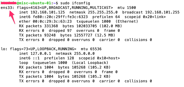
Step1: get the NIC name and number (ensXX)

$sudo ifconfig

This will display the network interface card details – let’s say the name and number is “ens33”:

Ifconfig-01

Step2: configure the NIC with IP address details by editing the YAML config file

Let’s say we configure “ens33” with “DHCP auto IP: config as following –

$sudo vi /etc/netplan/50-cloud-init.yaml

Enter the following details:

network:  
  version: 2  
  renderer: networkd  
  ethernets:    
    ens33:      
      dhcp4: true

If we want to add a “static IP address” – the do the following –

$sudo vi /etc/netplan/50-cloud-init.yaml

Enter the following details –

network:
  version: 2
  renderer: networkd
  ethernets:
    ens33:
      addresses:
        - 192.168.101.201/24
      gateway4: 192.168.101.254
      nameservers:
          search: [test.local, otherdomain]
          addresses: [8.8.8.8, 8.8.4.4]

Now you need to apply the new configurations; enter the following commands –

$sudo netplan try ;this command should return “Configuration accepted.”
$sudo netplan apply ;this command will apply the new setting based on the file
$sudo ifconfig ;this command will show you the IP address details

Do a ping to a remote machine.

Part 2: Get Ansible installed on your new Linux system

As a part of learning Linux sysadmin tasks – you will now learn package management! This is basically how to install/uninstall/update new software packages on a Linux system. Different Linux distributions (Redhat/Debian/Ubuntu/CentOS/…) use different tools for package management. I will show you how to install Ansible on Ubuntu/Debian based system.

There are two parts of Ansible –

  • Ansible Control Machine; this is from where you store you Ansible configuration files and control target systems
  • Ansible target machine or target nodes; Ansible support wide range of targets including Linux, Windows, Cisco, Juniper, Palo, F5, AWS, GCP, Azure, etc….

You need to install Ansible “only” on the controller machine; NO need to install Ansible in the target nodes. Ansible is agentless – so no Ansible client software provided for a target node.

Ansible installation details are available here on the official document site – https://docs.ansible.com/ansible/latest/installation_guide/intro_installation.html

Package management on Ubuntu is done via “apt” utility; we will install Ansible using “apt” on our new Linux machine; following are the commands.

$sudo apt-get update ;this will update the package list on the Linux
$sudo apt-get install software-properties-common ; this will install software name “software-properties-common”
$sudo apt-add-repository --yes --update ppa:ansible/ansible ;this will add new software repository
$sudo apt-get install ansible ;this installs the ansible packages along with its dependencies

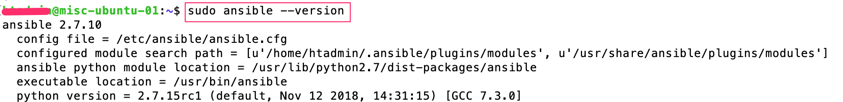
Enter command “$sudo ansible –version” to verify your installation.

show-ansible-version

Part 3: Let’s play with Ansible – Final Part

In this part I am covering how to use manage remote networking devices using Ansible.

There are two key files when playing with Ansible:

  • Inventory file ; this file contains list of remote devices
  • YAML playbook file/files; these files contain list of “tasks” to be applied onto the remote devices listed on the inventory file

YAML playbook “tasks” are defined within Ansible “modules”; let’s see the example following:

  • you want to send “show” commands to Cisco IOS devices, so you need “ios_command” module installed in your Ansible
  • you want send configuration commands to Cisco IOS devices to configured interfaces/routing, so you need “ios_config” module installed in your Ansible

If you don’t have “ios_config” module installed – then you will not be able to configure Cisco IOS devices using Ansible! Good news is default Ansible installation comes with hundreds of pre-installed modules including Cisco IOS, Cisco ASA, Juniper JUNOS, Palo Alto PanOS, AWS, GCP, Linux, Windows etc. Ansible is giving you option to create your own module in-case if you couldn’t find a module for a new type of device/software/system.

Following command list available installed modules in Ansible:

$ansible-doc -l | grep ios ;this will list all Cisco IOS modules
$ansible-doc -l | grep nxos ;this will list all Cisco NXOS modules
$ansible-doc -l | grep panos ;this will list all Palo PANOS modules
$ansible-doc -l | grep junos ;this will list all JUNOS modules

Ansible website has comprehensive details on every module; have a look at the “ios_config” module official page at -https://docs.ansible.com/ansible/latest/modules/ios_config_module.html?highlight=ios_config

Apart from the above inventory and YAML playbook file types – the main Ansible system parameters configuration file is “/etc/ansible/ansible.cfg”.

Step1: Ansible inventory file

Let’s have a look – what we can enter onto the “inventory” file; this file looks like following –

#Note – My list of Network Devices – Cisco/Juniper/Palo

csr-1000v-01   ansible_host=192.168.101.125
csr-1000v-02   ansible_host=192.168.101.126
sw-tst-01      ansible_host=192.168.101.131
sw-tst-02      ansible_host=192.168.101.132
asa-tst-01     ansible_host=192.168.101.135

[csr-routers]
csr-1000v-01
csr-1000v-02

[switches]
sw-tst-01
sw-tst-02

[asa-fws]
asa-tst-01

[routersnswitches]
csr-routers
switches

Based on the above –

  • The first part is the name/identification of the remote device; “ansible_host” is the variable name with a value of an IP address to send connection requests to the remote device (this could be be FQDN or hostname instead of IP address).
  • Secondly, we have created three groups – csr-routers/switches/asa-fws.
  • Lastly, we put all the three groups onto a new group/big group “routernswitches”.

By default, there is another group there called “all” – this includes ALL the devices in the inventory list; you don’t need to define “all” separately.

Cool – now we have got our inventory file ready!

Important Note: Ansible is agentless – then how it is going to talk to the remote systems? The answer is – for Linux/Cisco IOS/NXOS/JUNOS and similar Ansible use SSH connection. For Windows based targets Ansbile use PowerShell Remote Admin windows feature!

Step2: Ansible YAML playbook file/files

Once the inventory file is ready – next step is to create Ansible playbook. Question is what is a playbook, what is it’s role? Well – a playbook contains list of actions/tasks to be performed onto the remote devices; each of the action is called a “play”. While creating a playbook you need to define the workflow of tasks in “correct order” to be automated then convert them to different “plays” within an Ansible playbook file. Playbooks are written on YAML syntax.

As a network engineer you are already familiar with what steps it takes to setup two routers with OSPF; let’s break it down into multiple tasks (aka plays) –

  • Task 1: setup common parameters such as hostname/dns server/etc (Play 1)
  • Task 2: setup network interfaces with IP address on both the router (Play 2)
  • Task 3: setup ospf parameters on both the routers (Play 3)
  • Task 4: return/display “show run” on both (Play 4)
  • Task 5: return/display “show ip interface brief” (Play 5)

[Note: make sure to setup SSH and a network interface on both the routers so that Ansible controller can connect to both the above routers]

We can put together all the above plays (play 1 to 5) onto Ansible YAML playbook file and push to both the routers at the same time!

Before proceeding to YAML syntaxes – you “should” learn the following YAML items:

  • YAML “directory” items
  • YAML “list” items

Let’s create our first YAML script now!

Task A: Display “show run” and “show ip interface brief”

We want to display the above show from the “csr-1000v-01” and “csr-1000v-02” listed on our inventory file we have created earlier.

-
  name: Test playbook to return “show” command from Cisco CSR 1000v
  hosts: csr-routers
  connection: local
  vars:
    cli:
      username: cisco
      password: cisco
  tasks:
    - name: Print running config (play1)
      ios_command:
        provider: "{{ cli }}"
        commands:
            - show run
      register: show_run
    - debug:
        var: show_run

    - name: Print ip interfaces (play2)
      ios_command:
        provider: "{{ cli }}"
        commands:
            - show ip interface brief
      register: show_int
    - debug:
        var: show_int

Let’s do a debrief of the above YAML syntax:

YAML item name What is does?
name: Test platbook to return… this is just a name to identify the YAML playbook file
hosts: csr-routers this is the host group we configured in the inventory file, this can be a single device or “all” for all the devices within the inventory file list as well
connection: local this tells where to execute this YAML playbook file, in this example we are executing this on the local Ansible controller running Linux
vars: cli: …. we define this variable for username and password to connect to the remote CSR routers, otherwise we need to define this every time we want to run a play
tasks: list of plays starts from here
ios_command: this is pre-defined Ansible module created using Python; Cisco IOS show command details are listed here in this module
provider: this tells Ansible to use the pre-defined variables (cli with username/password) while sending remote connection requests to remote device
command: the actual Cisco IOS command
register: this tells Ansible to capture the command output within Ansible in a variable name defined in the register section
debug: var: this tells Ansible to display the previously captured register value what is stored in the register variable

Let’s create the Linux files and execute the above playbook with the inventory list –

$sudo mkdir /opt/ansible-cisco-practice
$cd /opt/ansible-cisco-practice
$sudo vi my-first-playbook-cisco.yaml ;copy and paste the above YAML contents
$sudo vi inventory.txt ;copy and paste the inventory file contents here

$sudo ansible-playbook my-first-playbook-cisco.yaml -i inventory.txt

Based on the above the “ansible-playbook” is the command name to execute a YAML playbook file; the option “i” specify the location of the inventory list file.

You might end-up seeing Ansible error message showing “unable to connect” to remote devices using SSH due to “SSH host fingerprint” issue – by default SSH validates host fingerprint for security. Two options to get this fixed as following:

  • manually send a connection request to the Cisco IOS device from the Ansible controller Linux via SSH – this will add the IOS device SSH fingerprint onto the Linux on the very first connection request.
  • Or update the Ansible system parameter configuration file to tell Ansible “not to validate” SSH host fingerprint; edit the “/etc/ansible/ansible.cfg” file and uncomment the following parameter and the re-run the “ansible-playbook” command with inventory file:
$sudo vi /etc/ansible/ansible.cfg

#host_key_checking = False  ;remove the hash # from this line
host_key_checking = False

You should be able to see Ansible is connecting to both the Cisco CSR routers mentioned and executed Play1 and Play2 with the “show” commands outputs!

You are nearly there! Now you know how to setup Ansible and get commands executed on remote Cisco IOS devices! Congratulations!

Task B: Configure Cisco an Interface and few OSPF parameters

You want to send the following configurations to both the CSR routers:

On “csr-1000v-01”:

!
interface G2
  description “connected to Router XX”
  ip address 172.16.100.51 255.255.255.0
  no shut
!
router ospf 100
  passive-interface G1
  network 172.16.100.0 0.0.0.255 area 0
!

On “csr-1000v-02”:

!
interface G2
  description “connected to Router XX”
  ip address 172.16.100.52 255.255.255.0
  no shut
!
router ospf 100
  passive-interface G1
  network 172.16.100.0 0.0.0.255 area 0
!

On both “csr-1000v-01” and “csr-1000v-02”:

!
ip name-server 8.8.8.8
ip name-server 8.8.4.4
ip domain-name test.local
!

Let’s create the Ansible YAML playbook file with the above:

-
  name: Test playbook – IOS Configs for Cisco CSR 1000v
  hosts: csr-routers
  connection: local
  vars:
    cli:
      username: cisco
      password: cisco
  tasks:
     - name: Configure TopLevel IOS configs DNS/DomainName on Both (Play1)
       ios_config:
         provider: "{{ cli }}"
         lines:
            - ip name-server 8.8.8.8
            - ip name-server 8.8.4.4
            - ip domain-name test.local

    - name: Configure GE2 interface on csr-1000v-01 only (Play2)
      when: ansible_host == "192.168.101.125"
      ios_config:
        provider: "{{ cli }}"
        lines:
            - description "Connected to Router XX"
            - ip address 172.16.100.51 255.255.255.0
            - no shutdown
        parents: interface G2

    - name: Configure OSPF 100 on csr-1000v-01 only (Play3)
      when: ansible_host == "192.168.101.125"
      ios_config:
        provider: "{{ cli }}"
        lines:
           - network 172.16.100.0 0.0.0.255 area 0
           - passive-interface G1
        parents: router ospf 100

    - name: Configure GE2 interface on csr-1000v-02 only (Play4)
      when: ansible_host == "192.168.101.126"
      ios_config:
        provider: "{{ cli }}"
        lines:
            - description "Connected to Router XX"
            - ip address 172.16.100.52 255.255.255.0
            - no shutdown
        parents: interface G2

    - name: Configure OSPF 100 on csr-1000v-02 only (Play5)
      when: ansible_host == "192.168.101.126"
      ios_config:
        provider: "{{ cli }}"
        lines:
           - network 172.16.100.0 0.0.0.255 area 0
           - passive-interface G1
        parents: router ospf 100

     - name: Save configs on both CSRs (Play6)
       ios_config:
         provider: "{{ cli }}"
         lines:
            - do write

    - name: Lastly display “show run” on both CSRs (Play7)
      ios_command:
        provider: "{{ cli }}"
        commands:
           - show run
      register: show_run
    - debug:
        var: show_run

Let’s demystify the above YAML script –

Play Name Ansible Module Used Target CSR Router
Play1: TopLevel IOS configs DNS/DomainName ios_config Both CSR routers
Play2: Configure GE2 interface with IP ios_config csr-1000v-01 only
Play3: OSPF 100 Configuration ios_config csr-1000v-01 only
Play4: Configure GE2 interface with IP ios_config csr-1000v-02 only
Play5: OSPF 100 Configuration ios_config csr-1000v-02 only
Play6: Save configs ios_config Both CSR routers
Play7: display “show run” ios_command Both CSR routers

We have used “condition when” here to push configurations to specific routers.

Let’s say – we save the above YAML syntaxes on a file called “my-second-playbook-cisco.yaml”; we can now execute this playbook –

$cd /opt/ansible-cisco-practice
$sudo vi my-second-playbook-cisco.yaml ;copy and paste the above YAML contents

$sudo ansible-playbook my-second-playbook-cisco.yaml -i inventory.txt

You should see the playbook execution results and “show run”. Screenshot following:

PlayBook-Execution-01

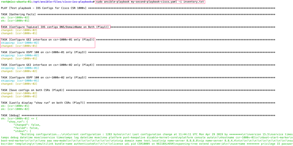
See the “changed” and “skipping” in the output above; this is because we used condition “when”.

Task C: Let’s take a backup of IOS device configs from “show run”

This is very simple; most of YAML syntax are based on the first YAML script “my-first-playbook-cisco.yaml” for this backup job. In this example – we will tell Ansible to save the “register: show_int” output onto a TXT file for both the CSR devices.

-
  name: Playbook to backup configs of Cisco CSRs
  hosts: csr-routers
  connection: local
  vars:
    cli:
      username: cisco
      password: cisco
  tasks:
    - name: Print running config – csr-1000v-01 (play1)
      when: ansible_host == "192.168.101.125"
      ios_command:
        provider: "{{ cli }}"
        commands:
            - show run
      register: show_run_csr-1000v-01

    - name: save output to /opt/ios-backups - csr-1000v-01 (play2)
      when: ansible_host == "192.168.101.125"
      copy:
          content: "{{ show_run_csr-1000v-01.stdout[0] }}"
          dest: "/opt/ios-backups/backup_{{ ansible_host }}.txt"

    - name: Print running config – csr-1000v-02 (play3)
      when: ansible_host == "192.168.101.126"
      ios_command:
        provider: "{{ cli }}"
        commands:
            - show run
      register: show_run_csr-1000v-02

    - name: save output to /opt/ios-backups - csr-1000v-02 (play4)
      when: ansible_host == "192.168.101.126"
      copy:
          content: "{{ show_run_csr-1000v-02.stdout[0] }}"
          dest: "/opt/ios-backups/backup_{{ ansible_host }}.txt"

Now execute the above playbook; our YAML name file for Cisco IOS back is “cisco-ios-backup-playbook.yaml” –

$sudo mkdir /opt/ios-backups
$cd /opt/ansible-cisco-practice
$sudo vi cisco-ios-backup-playbook.yaml       ;copy and paste the above YAML contents
$sudo ansible-playbook cisco-ios-backup-playbook.yaml -i inventory.txt
$cd /opt/ios-backups
$ls -la

You should be able to see two backup files in the directory “/opt/ios-backups”; run the “cat” command to see the contents of these files. Your backups are done!

What is NEXT?

Once you are familiar with Linux and Ansible YAML – you next step on NetOps should be following:

  • Learn GIT and GitHub. GIT is source code version control system for your YAML scripts. I will write a separate post on this later.
  • Learn Ansible Tower or similar such as Foreman or Ansible Semaphore UI; this will give you huge control over your centralised Ansible orchestration, visibility, control, reporting and many more.
  • And obviously learn Ansible advanced details (keep exploring different Ansible modules on official Ansible web site).


Application Whitelisting on Windows and App Execution Analytics (using AppLocker, AppIDSvc and Splunk)

If you familiar with security compliance requirements such as PCI DSS or HIPAA – one of the requirements is “application whitelisting”. Application whitelisting is the solution that allows execution of pre-approved apps and scripts only and disallow rest.

Application whitelisting can be done using many tools – in this example I will discuss how to get application whitelisting done using in-build Windows tools; I will use Windows AppLocker utility to implement application whitelisting. I will discuss setting up Splunk for AppLocker, so that we get real time visibility/analytics of application whitelisting and alerting.

This HOWTO got two parts –

Part 1 – this discuss technical steps regarding how to setup application whitelisting on Windows platform and push the settings to bunch of windows computers.

Part 2 – this discuss technical steps regarding how to get visibility, analytics and alerts about the application whitelisting using Splunk (e.g. application whitelisting logs showing which apps are allowed, which are denied, who executed the app, when, from where etc).

Part 1 – Setting up the Application Whitelisting on Windows

Following are the steps for Part 1.

Step1: Start the “Application Identity” (AppIDSvc) service & set to start automatic

AppIDSvc service is a Microsoft service used by AppLocker to determine and verify the identity of an application. Without AppIDSvc AppLocker is unable to determine and verify application, scripts, installers and executables.

AppWhitelist1-AppIDSvc

Step2: Setup Application Whitelisting using “Local Group Policy Editor” or “Group Policy Management Console”

AppLocker settings are available within “Computer Configuration -> Windows Settings -> Security Settings -> Application Control Policies -> AppLocker”. In an ideal environment all the AppLocker settings should combines into a single Group Policy Object (GPO) and pushed onto computers via Active Directory.

Set the policy “Enforcement rules” first

Right click on the AppLocker -> go to Properties -> Select “Enforcement rules” for both Executables and Scripts. Enforcement rule enforces “allow” and “deny” operations.

“Executable rules” are applied to application programs installed on the Windows OS.
“Scripts rules” are applied to all scripts available on the Windows OS.

“Audit only” – this setting does not prevent execution rather it generates audit logs only about what items are executed on the Windows OS and who executed it.

AppWhitelist2-AppLockerProperty

Set the Executable Rules

Set allow or deny action to executable application here; few options available here –

Executable Rules based on “Publisher” – allow all signed software by authorised publisher.
Executable Rules based on “Path” – allow specific file or folder. I prefer this.
Executable Rules based on “File hash” – this is for application which are not sighed.

Example screenshot of “Executable Rules” – in this example users (everyone) are allowed ONLY to execute “7-Zip” and “Notepad++” which are installed within “C:\Program Files\” or “C:\Program Files (86)\”; whereas “Administrators” can execute all; there is a “Deny” by default for rest.

Interestingly the same variable “%PROGRAMFILES%” returns both “C:\Program Files\” & “C:\Program Files (x86)”.

AppWhitelist3-LocalGPO

Following screenshot example shows default “Executable rules” which permits everything along with a rule to deny “Google Chrome” for everyone including Administrators; deny overrides other options.

AppWhitelist4-LocalGPO2

Set the Script Rules

Script rules options are same as the executable rules – Publisher, Path and File Hash along with Allow or Deny. Also, you can create default rules which allows everything.

Following “Script Rules” screenshot shows the same BAT file “TestBATScript.bat” is allowed on the %OSDRIVE% which is the “C:\Scripts” for users and denied on the “E:\Scripts\” for everyone.

AppWhitelist5-LocalGPO3

If the above settings are pushed via GPO – it requires some time to applied to the destinations computers. This can be forced or the destination computer can be rebooted to get these settings immediately pushed.

Also, if we remove AppLocker settings on a computer – this takes few minutes (2-5min) to take effect as well; don’t expect result immediately.

Step3: Verification

As we have configured “Deny” on the “Google Chrome” for all users – it will pop-up with the following error message when someone tries to open it up –

AppWhitelist6-ErrorChrome

Also, we have configured the “TestBATScript.bat” to allow execute from “C:\Scripts” and deny from “E:\Scripts\”; following screenshot says it all –

AppWhitelist7-ErrorScripts

Part 2 – Visibility and Analytics of Application Whitelisting using Splunk

A complete real time visibility and analytics of application executables and scripts across all the servers (100+ servers) are important to support the platform. Following are interesting items to application whitelisting analytics –

  • Who is executing what application
  • On what servers/system
  • What application are allowed
  • What application are denied
  • When/What time an application executed
  • Knowing the system applications
  • Knowing user defined applications
  • Sending alert email when an application/script execution is blocked

The above key interesting items about application whitelisting are available within AppLocker Windows Event Log files; the location of these logs are at Event Viewer -> Application and Services Logs -> Microsoft -> Windows -> AppLocker (EXE and DLL; MSI and Script). Example screenshots are following –

AppWhitelist8-EventLogs

AppWhitelist9-EventLogs2

To get real time analytics of what’s happening within AppLocker onto Splunk – we need to redirect AppLocker logs onto -> Splunk using the “Splunk Universal Forward”.

Setup Splunk Universal Forwarder (SUF)

SUF is free downloadable from www.splunk.com; download and install it on the target Windows computer. Ideally, it should be part of base Windows OS build template – so that we don’t need to install it manually every time.

During the SUF installation – we select the following “Security Log” only; although this is not a requirement for AppLocker to select security log; however, selecting security logs fulfil many compliance requirements. Select other type logs based on business requirements; also event logs selection can be done later on after the installation.

Make sure your Splunk server is up and running.

[select Windows Event Logs]

AppWhitelist10-SUF1

Enter the Splunk server IP address and receiving port number to redirect logs to.

[Enter the destination Splunk receiving server and port number]

AppWhitelist11-SUF2.png

After the installation – add the following lines onto the SUF local site config file “C:\Program Files\SplunkUniversalForwarder\etc\system\local\input.conf” –

[WinEventLog://Microsoft-Windows-AppLocker/EXE and DLL]
disabled = 0
evt_resolve_ad_obj=1

[WinEventLog://Microsoft-Windows-AppLocker/MSI and Script]
disabled = 0
evt_resolve_ad_obj=1

The above lines will redirect AppLocker “EXE and DLL” and “MSI and Script” logs onto -> Splunk; the “evt_resolve_ad_obj=1” will allow identify/show Active Directory user names.

Restart the SUF service.

At this stage AppLocker logs will start flowing onto the Splunk; based on index settings Splunk will automatically add these log entries onto the respective index or to the default index.

Following are few examples of AppLocker analytics dashboards within Splunk –

Screenshot of who/what action/what application/when/from is following; Splunk search string for this:

source="WinEventLog:Microsoft-Windows-AppLocker/*"| table host, User, Type, Message, _time

AppWhitelist12-Splunk11

Screenshot of total number of applications following; Splunk search string for this –

source="WinEventLog:Microsoft-Windows-AppLocker/*"| chart count by Message

AppWhitelist13-Splunk22

Screenshot of total number of denied applications is following; Splunk search string for this –

source="WinEventLog:Microsoft-Windows-AppLocker/*" Type=Error| chart count by Message

AppWhitelist14-Splunk33

Screenshot of email alert when there is a deny following; Splunk search string is following –

source="WinEventLog:Microsoft-Windows-AppLocker/*" Type=Error | table host, User, Message, _time

AppWhitelist15-Splunk44

[Screenshot of Splunk alert email triggered on deny condition]

AppWhitelist16-Splunk5Main

One of the key reason for alert emails – incase any “required” apps missed out from whitelisting – you will get details of the app even before the end user/team tells you to whitelist it.

Thats ALL!


AWS VPC Networking – discussing all type of VPC network “GATEWAYS” (part 1)

I was discussing AWS VPC networking and how network traffic come in/out to a VPC from different destinations with my team. Then later I though – lets put it on my blog – this will help others as well. I am discussing VPC gateways from a typical network engineer’s point of view.

There are many different type of gateways (network routers) on AWS VPC networking. Each of them have different roles – you put together different gateways to make a complete solution. Gateways are key components of a routing table – here I will show all the gateway items available on a “VPC routing table”.

Following diagram shows all the different types of gateways/routers on AWS VPC platform (follow the traffic path arrow head):

AWS-VPC-Gateways

Lets discuss the key attributes (what are they? what they can do?) of the VPC gateways:

i. Virtual Private Gateway (VGW-nn)
This is a multi-purpose network gateway appliance provides in/out routing to a VPC. Key attributes of VGW:

  • this is a multi-purpose network gateway appliance provides in/out routing to a VPC
  • the destination networks can be via AWS DirectConnect to a self-managed data centre or can be over IPSec VPN (via AWS VPN connections)
  • for IPSec VPN – an AWS “VPN connection” object need to be attach to VGW
  • for IPSec VPN – supported routing protocols are BGP and Static
  • for AWS DirectConnect connection – VLAN tagged virtual interfaces (VIFs) are needs to be created for IP routing and attached to VGW
  • for AWS DirectConnect connection – BGP is only supported routing protocol
  • when more then one interfaces available ECMP is configured by default for both IPSec VPN and DirectConnect while sending traffic from AWS to a remote destination
  • BGP path selection can be manipulated by “AS path prepending” sending from the source to AWS
  • “VGW” instances are available within VPC routing table to be set as target

ii. Customer Gateway (CGW-nn)
CGW are part of IPSec VPN connectivity to a VPC. Key attributes are following:

  • CGW represent remote end VPN gateway
  • AWS “VPN Connections” are required to attached a CGW to itself
  • without having a CGW “AWS VPN Connection doesn’t know where to send traffic to

iii. Internet Gateway (IGW-nn)
Key attributes of IGW are following:

  • provides internet in/out (both way) to a VPC and its contents
  • provides inbound Internet to Elastic Load Balancer
  • provides internet access to L4-L7 network appliances (F5 BIP-IP, Cisco ASAv, Juniper SRX etc)
  • provides internet access to VPC NAT GW
  • outbound traffic from a VPC can be sent out via either IGW or via VPC NATGW (will discuss this in next part2 – VPC routing tables and subnets)
  • AWS Elastic IP address rateability to an VPC object are done via IGW
  • “IGW” instances are available within VPC routing table to be set as target

iv. VPC NAT Gateway (NAT-nn)
Key attributes of VPC NATGW are following:

  • provides NAT outbound only (one direction) to VPC and its contents
  • NAT Internet access is done via an IGW
  • NAT can not access Internet directly (without having an IGW)
  • “NAT” instances are available within VPC routing table to be set as target

There are lot security requirement scenarios where you allow internet access for systems/servers only via NATGW; no inbound are permitted and local systems are kept fully local only.

v. Layer4-Layer7 network appliances as Gateway
These are basically an EC2 instance with 2 or more NICs providing network connectivity.
Key attributes are following:

  • cloud network admins have flexibility to deploy their own network appliance (F5, Cisco, Juniper, Sophos, Barracuda etc)
  • even an EC2 instance of any OS (Linux/Windows) with 2 x NICs can be converted to a routing device/NAT appliance (need to disable Source/Destination Check under EC2 Networking)
  • this type of device rely on IGW to route traffic to internet (just like the NAT gateways)
  • this type network appliance can provide both in/out traffic (via NAT translation or Proxy) to VPC and its contents
  • this type network appliances (EC2 instances) are available within VPC routing table to be set as target

vi. VPC Peering (PCX-nn) 
A special type of gateway for inter-VPC communication. VPC peering are used when creating inter-connect between VPCs. Following are attributes of VPC peering network:

  • provides peer-to-peer connectivity to two VPCs only
  • in a scenario where “VPC A” peers to > “VPC B” and “VPC B” peer to > “VPC C” – “VPC A” can not talk to “VPC C”
  • does not provides transit path
  • in above scenario “VPC B” cannot be used as a transit route for VPC A to > VPC C
  • “pcx” are available within VPC routing table to be set as target

In the next part I will be discussing VPC “subnets” and “routing tables” which are capable to cater complex segregated routing requirements on AWS platform.

Cisco Nexus vPC and non-vPC VLANs together on the same platform (Nexus hybrid setup) – NXOS v7.0(3)4(1)

Cisco discontinued “spanning-tree pseudo-information” starting from NXOS version 7.0(3)4(1) on the 9000 platforms. So what is the solution for Nexus vPC and non-vPC VLANS on the same platform (hybrid)? Is it no longer going to be supported on NXOS/9000 platforms?

Although hybrid is not recommended vPC design for “aggregation layer” but you find a lot scenarios where you need to have both vPC and non-vPC within the same platform (mostly in mid-size data centres; where you have a lot reasons you can’t deploy traditional ethernet switches; hence you have considered the Cisco Nexus platforms).

If you carry everything (both vPC VLANs and non-vPC VLANs) over the vPC peer-links (yes, vPC carry orphaned VLANs as well!) – in this case if there is any issue happen on the vPC peer links and that stops the vPC working, the downstream switches those are connected to the Nexus via non-vPC/non-vPC VLANs will stop forwarding frames due to STP (any STP – STP/RSTP/PVSTP/MSTP) blockage as they don’t have any information about what happened between the vPC peer Nexus switches in a vPC peer failed scenario.

Experts suggest that you should have an additional Layer 2 trunk port-channel alongside your vPC peer-link; this Layer 2 port-channel will carry non-vPC VLANs in case vPC stops working (whatever reason; could be a Nexus reboot during maintenance!).

Well, now you have setup a seperate Layer 2 trunk port channel for non-vPC VLANs and shutdown the vPC peer link to test it – but you found it is still not working as expected! STP is blocking the Layer 2 trunk link, whats the problem! Cisco used to have a solution for this called “spanning-tree pseudo-information“; as I have mentioned in the beginning Cisco discontinued this starting from version 7.0(3)l4(1) on the Nexus 9000 platform. So what is your option for this? Should you stop using Nexus if you don’t follow spine and leaf design?

Yes – there is an answer to this, there is a small trick to make this working! By discontinuing psuedo-information, Cisco basically makes it ever easier to configure; you need to do the following –

i. First, you need to set STP root priority for the VLANs to a lower priority number on one of Nexus switch (default priority is 32768, lower is prefer; this should be done on the primary vPC role Nexus switch) and leave STP untouched on the other Nexus switch (this is the vPC secondary role switch).

ii. Second, on the non-vPC trunk port-channel set “spanning-tree port type normal” on “both” the switches; (“spanning-tree port type network” is recommended for vPC peer-link).

Here is an example config -Here is an example config –

On the vPC primary role switch, apply the following -

(config)#spanning-tree vlan 10,20,30,40-50 priority 8192

On both the switches, apply the following -

(config)#interface port-channel10
(config-if)#description "non-vPC trunk port" 
(config-if)#switchport 
(config-if)#switchport mode trunk 
(config-if)#switchport trunk allowed vlan 10,20,30,40-50 
(config-if)#spanning-tree port type normal

Without having the above configuration applied you will find STP is blocking the non-vPC Layer 2 trunk link even if the vPC peer-link is shutdown. Also in this example – the vPC primary role switch will be the STP “root bridge” because of lower priority configured (8192).

To test your configuration – shutdown the vPC peer-link, run “show spanning-tree vlan xxx” – you should see STP put the L2 trunk interfaces in forwarding state immediately.

Here is a vPC and non-vPC VLANs on the same platform diagram –

CiscoNexus-Hybrid


Cisco UCS Platform Emulator – UCSPE 3.1(2ePE1)

Cisco UCS Platforms are expensive kit to play with. UCS Platforms are not just a standalone router, switch or a firewall that could easily be emulated on a PC – they are bunch of kits interconnected together to deliver the UCS platform. UCS is not a server – it’s a system or a platform compared to traditional computing; UCS comes with unified (LAN/SAN/FC/FCoE/HBA/others) and stateless computing together.

Cisco has come up with a solution to help engineers to get their hands dirty on UCS Platforms – the solution is called Cisco UCS Platform Emulator (UCSPE). The latest UCSPE is version 3.1(2ePE1). Cisco made UCSPE available to everyone – you only need to have a Cisco login.

The whole UCSPE comes with the following-

i. 2 x Fabric Interconnect (Model: UCS-FI-6332-16UP)
ii. 2 x FEX (Model: Nexus 2348UPQ N2K-C2348UPQ)
iii. 3 x UCS 5108 Chassis with 12 x different model blades
iv. 1 x UCSC C3X60 server (Model: UCSC-C3X60)
v. 7 x UCS C series servers (220/240/460)

The above are enough to emulate a complete decent size UCS Platform!

Yes! you can create bunch of full fledged “Service Profiles” with different configurations settings and applied them to the servers; also you can configure the fabric interconnect ports with different options (LAN uplink/Server uplink/FC/FCoE/NAS/Port Channels etc)

UCSPE comes in “OVA” and “VMware VMX/VMDK” format (in a ZIP file); you can run it on VMware Workstation or Fusion (I use Fusion).

The pre-defined OVA/VMX requires only one (01) vCPU, 1024MB memory and 3 x vNICs.

You need 3 x IP address (could be from DHCP or static) to make it accessible – one IP address is for Fabric Interconnect “A”, second one is for Fabric Interconnect B and the third IP address is the VIP of FI-A and FI-B Cluster.

Thats all! Its a great tool for candidates learning towards CCNA/CCNP/CCIE Data Centre certifications as well.

UCSPE download link is the following:
https://communities.cisco.com/docs/DOC-71877

Following are few screenshots:

UCSPE-VM-1

[UCSPE VM console]

UCSPE-Platform-01

[UCSPE devices list. They covered a lot devices in here! The red arrow is showing the icon of UCSM – you need to click on this to launch UCSM]

UCSPE-Platform-02

[UCSM – Login Screen]

UCSPE-Platform-Topology-01

[UCSM- The Topology]

UCSPE-Platform-Fabric-A-01

[UCSM- FI “A”]

UCSPE-Platform-01-5108-Chassis

[UCSM – UCS 5108 Chassis]